
A global leader in the development and manufacturing of specialty polymers and biobased chemicals, based in the Dover, OH area, approached C-P Systems to conduct a relief study on two Wiped Film Evaporator (WFE) systems used in processing hot melt adhesives. The facility housing these systems was a recent acquisition and required an extensive review of overpressure protection systems. The project’s goal was to conduct a relief study aimed to ensure compliance with API 520/521 standards for pressure relieving and depressuring systems, along with providing comprehensive documentation of relief system design and design basis to meet OSHA PSM requirements, specifically CFR 1910.119(d)(3)(i)(D).
The WFE systems, which included a mix of ASME code and non-code vessels, needed comprehensive safety controls and proper documentation to meet regulatory standards. Our role was to address documentation gaps, assess overpressure risks, and design an updated relief system to ensure the facility’s ongoing safety and compliance.
The client’s primary objectives were to ensure all equipment in their facility complied with API 520/521 standards. The facility housed a combination of ASME code and non-code vessels, with incomplete or outdated documentation, leading to uncertainty about overpressure scenarios and compliance. To resolve this, C-P Systems conducted new pressure rating calculations to ensure proper relief protection for the interconnected vessels.
Lack of thorough documentation is a common challenge for many manufacturing facilities. Aging facilities, plant expansions, personnel turnover, and changes in ownership leave gaps in the documentation, and on-site engineers are often already fully occupied with project loads and daily responsibilities. Routine process hazard reviews often uncover areas where facilities fall short of regulatory compliance, necessitating the need for relief studies and system modifications. In this case, the incomplete process safety information presented a significant hurdle, as it limited the ability to verify the adequacy of existing relief systems. Furthermore, the client needed to minimize production downtime during both the study and the implementation of any required changes.
C-P Systems implemented a two-phased approach to ensure a structured and efficient process, addressing the client’s compliance gaps while minimizing operational disruptions. The first step was to quickly identify the worst-case relief sizing scenario, which would define the most challenging relief requirement for the system. Focusing on the worst-case scenario early allowed us to establish a clear path for system upgrades without requiring the client to invest heavily in full system documentation at the outset.
This phased approach enables customers to prioritize efforts and manage budget more effectively, as it allows for early identification of critical issues without the need for significant upfront investment. The goal of Phase 1 is not to complete all documentation, rather to map out the project’s scope, develop preliminary cost estimates, and set priorities to ensure a more efficient progression into detailed engineering. This methodology accelerates project timelines by enabling customers to review scope, budget, and schedule before moving into the more detailed Phase 2.
Through this strategy, we provided the client with a clear roadmap that minimized rework, mitigated potential cost overruns, and allowed for flexibility in addressing additional priorities as they arose. This structured, stepwise approach ensured that the client could address safety concerns while maintaining operational continuity, ultimately resulting in a more efficient project progression.
At C-P Systems, we prioritize comprehensive information gathering at the outset of every project. For this project, this meant conducting a field survey, reviewing the P&IDs, and gathering critical stream data to ensure we had a complete understanding of the system’s current state. Working alongside the client’s operational team, we verified relief system parameters and ran preliminary calculations to identify gaps in protection.
Our analysis uncovered multiple vessels within in the system that lacked proper pressure rating documentation. We conducted pressure rating calculations on these vessels to ensure they were properly aligned with the rest of the system and that the relief devices would adequately protect against overpressure. Additionally, a dimerized fatty acid in the system had insufficient fluid property data for fire scenarios, so we collaborated with a partner to conduct VSP2 testing to assess the material’s behavior under fire exposure.
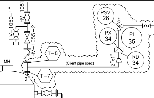
Figure 1 Section of the clients P&ID’s, detailing tie points, piping specifications, and added components
Typical list of overpressure scenarios analyzed:
Our Phase 1 report included conservative estimates on relief sizing based on worst-case scenarios. This approach allowed the client to budget for the most expensive possible outcomes, while leaving room for refinement and potential cost savings in later phases. The report also recommended adjustments to vessel pressure ratings and identified opportunities for safety improvements including relief valve upgrades and strategic system modifications.
By taking a conservative approach early in the project, we provided the client with a clear, actionable scope for the upcoming design and engineering work, ensuring compliance while keeping project timelines, costs, and priorities in check.
In Phase 2, we initiated a parallel path approach, beginning with a laser scan of the facility while simultaneously building upon the information gathered in Phase 1 to perform detailed engineering calculations. The laser scan provided precise as-built conditions of the facility, which were then integrated into a 3D facility model. This model allowed our designers to generate accurate piping isometrics based on actual plant configuration, while the engineering team focused on finalizing the sizing and specifications for relief valves, rupture discs, and associated piping, instrumentation, and valves.
| Inlet Piping | The pressure drop in the inlet piping is within typical limits such that the inlet pressure drop is less than 3% of the relief set pressure. |
| Outlet Piping | The pressure drop in the outlet piping is within typical limits such that the outlet pressure drop is less than 10% of the relief set pressure. |
| Pipe Stress Analysis | The amount of stress in the outlet piping is within typical limits such that no piping components will be stressed above piping code limits. |
| Reaction Forces | The outlet piping configuration is typical such that reaction forces imposed on the relief device and vessel nozzles are within code limits. |
Table 2 Results of Physical Layout Review
During this phase, our engineering team addressed some challenging configurations related to pump overpressure scenarios, which included a fluid recirculation loop with a main circulation pump and multiple in-line booster pumps, and equipment bypass configurations that could direct pump pressure to either end of a series of heat exchangers. By leveraging the information gathered in Phase 1, we were able to identify these unique situations, model any complex fluid dynamics and determined the appropriate solutions to ensure system safety.
As the 3D design progressed, we conducted collaborative design reviews in Navisworks with the client’s team. This allowed stakeholders to visualize the proposed piping modifications within the context of their existing facility, ensuring pipe routing that met the process demands as well as the maintenance and operational needs of the facility. We focused on minimizing welds and elbows, sloping pipelines as needed, and even utilizing existing wall penetrations where possible. The result was a reduction in pressure losses—avoiding unnecessary increases in line sizes and added installation costs.
The final deliverables included:
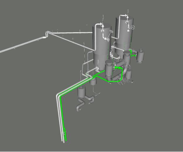
Figure 2 Overpressure Model – ISO view, looking northwest in the client’s facility
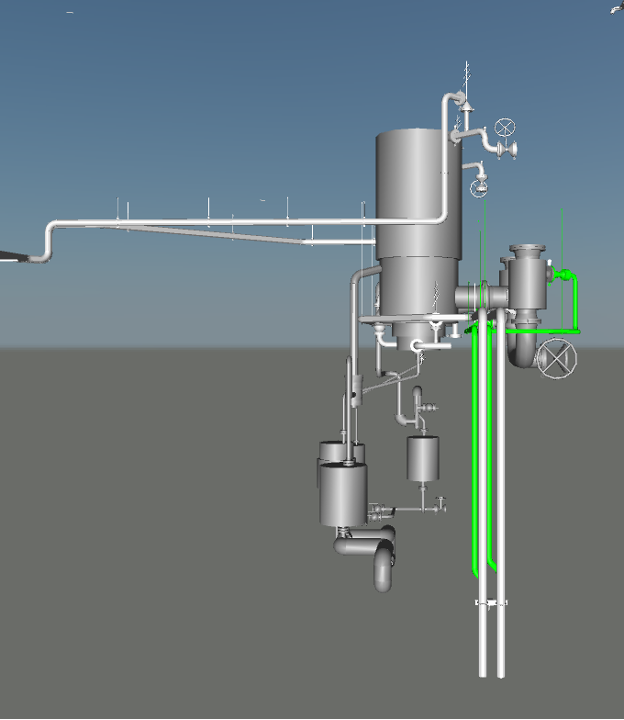
Figure 3 Overpressure Model – View looking north in the client’s facility
This comprehensive package allowed the client to secure mechanical installation bids and proceed with construction. C-P Systems typically leads bid reviews with mechanical contractors and remains available for installation and startup assistance as needed, ensuring a smooth transition from design through execution.
After receiving the client’s request for a relief study, we implemented a phased approach to ensure thoroughness and efficiency. The initial identification and planning phase overlapped with a large portion of the necessary work for the entire project, aiding in budgeting and scheduling while minimizing interruptions to the client’s production schedule.
A key component of this project was the need for precise as-built conditions to guide the design. To achieve this, we utilized our Leica RTC360 3D Laser Scanner, which provided a 3D point cloud of the facility accurate to 1.9 mm at 10 m, allowing us to confidently integrate any process modifications into the 3D facility model. This ensured that any modifications to the system fit seamlessly within the existing facility structures. It also allows for piping to be pre-fabricated off-site, minimizing construction costs and downtime.
Our team brought deep expertise in relief system design and chemical process engineering to this project, leveraging our internal industry veterans to tackle unique challenges with complex system configurations and unconventional fluid dynamics. This approach allowed us to effectively and efficiently navigate the more intricate aspects of the project, ensuring the best possible outcome.
At C-P Systems, we objectively consider all options when making recommendations—whether it’s cost, quality, newer technology, or plant standards. We collaborate closely with our clients, considering their preferred manufacturers where applicable while ensuring that our recommendations meet the highest standards for quality, cost-effectiveness, and long-term maintenance.

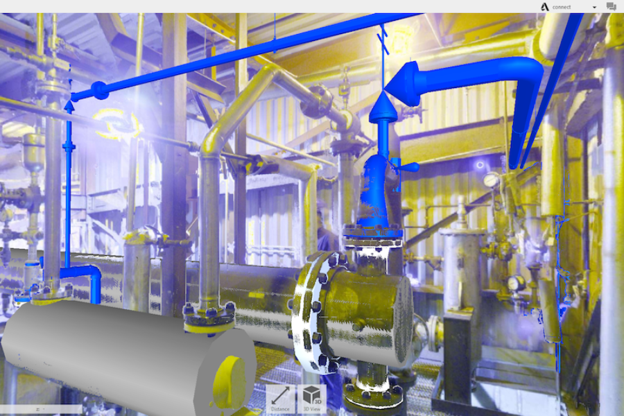
Figure 4 Laser scan with as-built and proposed pipe routing
C-P Systems successfully executed a relief study, documentation, and the associated process implementation, bringing these WFE systems into full compliance with both OSHA and API standards. By addressing documentation gaps, optimizing pressure relief systems, and employing advanced tools such as laser scanning, we were able to deliver a solution that minimized disruption to operations while maximizing safety and regulatory compliance.
The comprehensive mechanical construction package we provided allowed the client to implement the system upgrades smoothy and efficiently resulting in minimal downtime for operations. Upon project completion, the WFE systems met all regulatory requirements, and the facility was equipped with the necessary protections to prevent overpressure incidents.
Our collaborative approach, coupled with thorough documentation and cutting-edge design, received positive feedback from key client stakeholders. This success has led to continued partnerships with and C-P Systems on additional projects, where our expertise in compliance, safety, and operational efficiency remains critical.
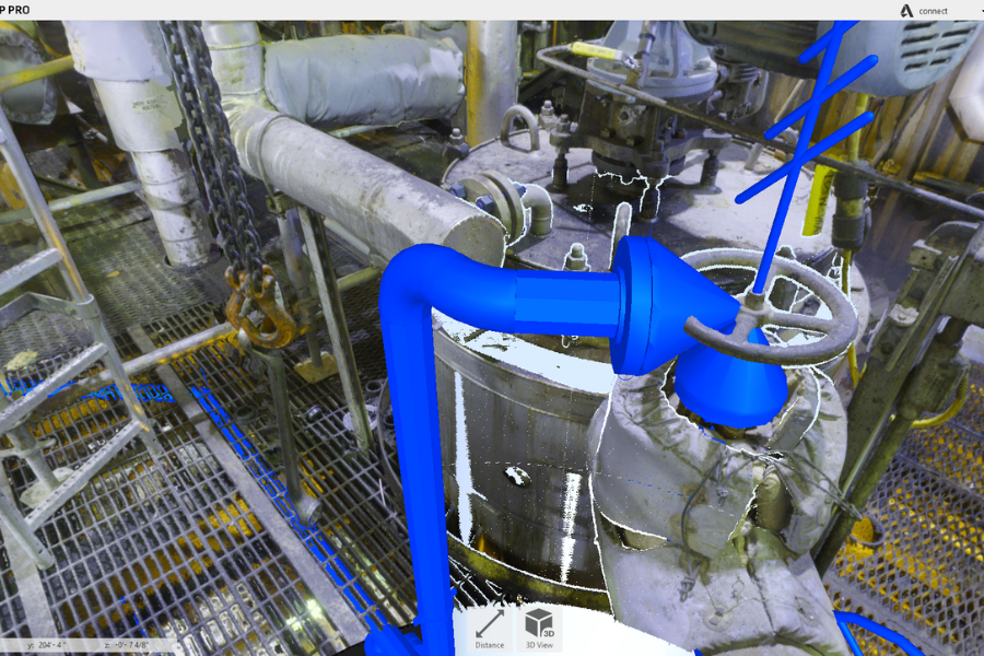
Figure 5 Model of new relief design placement, layered on the original laser scan of the client’s facility
“My experience working with C-P Systems on this project was extremely satisfying. Their level of organization and professionalism was the best I have been associated with and the attention to detail along with the knowledge of the code to get us to the correct results made the project run smoother and saved time by reducing unnecessary rework. The final packages are extremely complete and require little to no in field measurement verification. I try to use them on every project I work on.”
— Dan Kennedy, Principal Process Technology Engineer- Global Engineering at Kraton Chemical, LLC
Contact us today to discuss feasibility study options for your project.
