Process flow diagrams (PFDs) and piping and instrumentation diagrams (P&IDs) may look similar at first glance, but they serve very different purposes. Teams that blur the line between them often face rework, inefficiencies, and confusion. Understanding the difference between these two important diagrams and how they work together is key to keeping industrial projects on schedule and within budget.
A PFD provides the big picture of a process. It outlines what the process does: showing flows, pressures, temperatures, and composition. It includes key calculations that provide the process information used to determine equipment sizing criteria. A P&ID, on the other hand, provides the technical details. It shows how the system is built and controlled (including equipment, valves, and instruments) and focuses on implementation, operation, and maintenance.
You can build a P&ID from a solid PFD, but not the other way around. PFDs define what the system needs to do, while P&IDs show how to do it. Skipping a PFD can lead to oversized or misapplied equipment, missing control logic, and inefficient design that requires costly changes later.
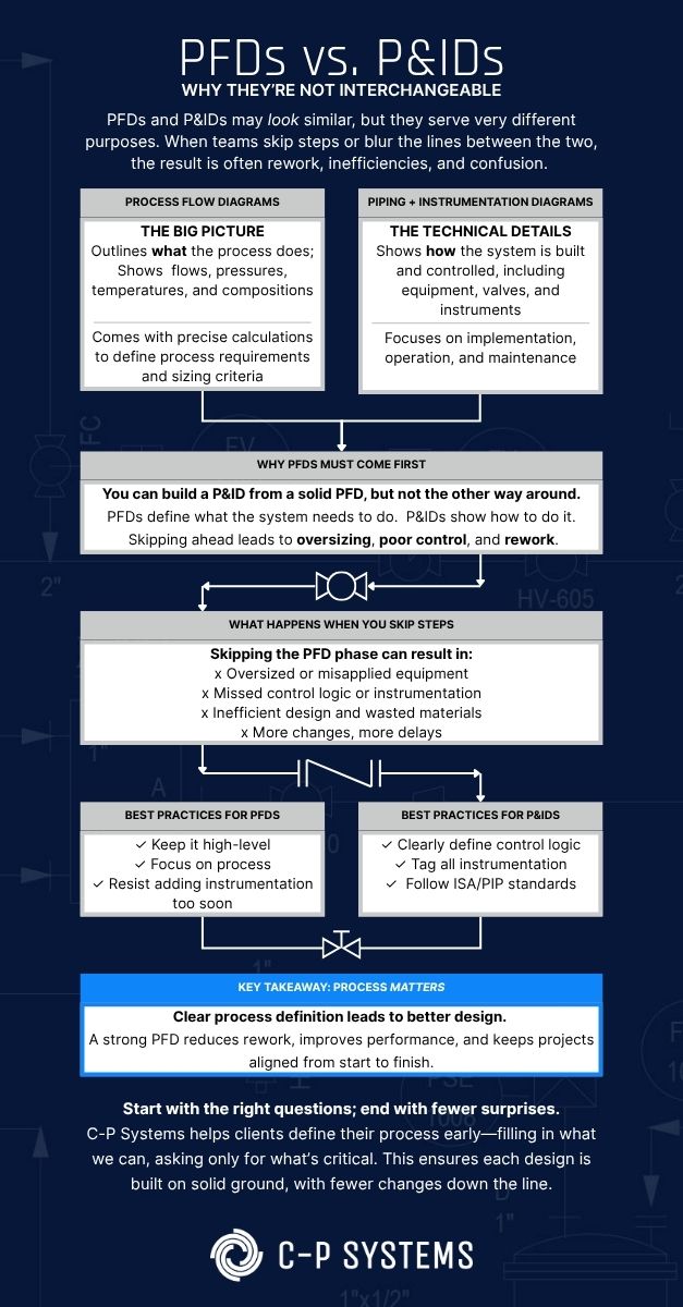
Figure 1. Process flow diagrams (PFDs) and piping and instrumentation diagrams (P&IDs) may look similar at first glance, but they serve very different purposes.
The Hidden Cost of Miscommunication
Even small gaps in understanding during design can lead to major issues in the field. PFDs and P&IDs translate complex process details into accessible information that keeps engineers, project managers, and contractors aligned.
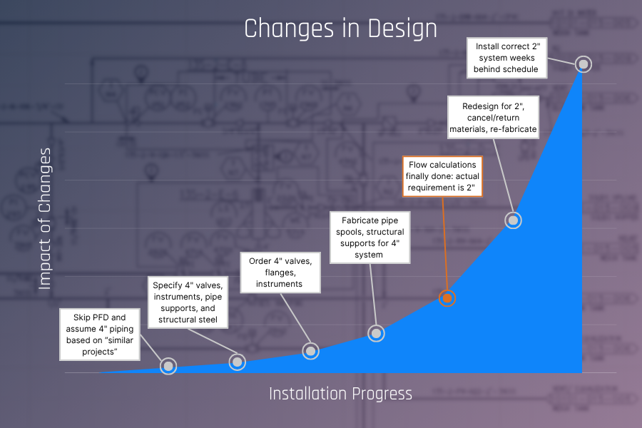
Figure 2. Early assumptions compound over time. When teams skip the PFD phase, errors in flow or sizing often surface late in the project. By the time materials are ordered and fabrication is underway, these mistakes can lead to significant cost and schedule impacts.
The Role of PFDs: Defining Process Intent and Setting Accuracy
A PFD captures the main components of a process (including equipment, flow paths, and control points) and shows how materials and energy move through a system, unit operation by unit operation. It serves as a roadmap for early design discussions, allowing stakeholders to validate objectives and identify potential risks before detailed design begins. The review of the process-side information during the PFD phase also establishes the basis for utility requirements, which should result from this analysis rather than from early assumptions. This approach ensures that utility systems are correctly sized and function as intended to support process operations.
When process flow data is incomplete, engineers use industry experience to make informed assumptions that keep design moving forward. Still, it’s important to work quickly to validate those assumptions once data becomes available, reducing the chance of errors or rework later in the project.
The PFD establishes target conditions for each flow and identifies where higher measurement accuracy may be required, which drives downstream instrument and control design. Over-specifying accuracy adds unnecessary cost, while under-specifying it leads to performance issues. For example, specifying ±0.1% accuracy on a non-critical flowmeter adds cost with no measurable benefit. Aligning on accuracy early has a direct impact on budget and operability.
The Role of P&IDs: Turning Design Intent into Action
If a PFD defines what the process does, the P&ID defines how it operates. Developed according to client or other industry standards, a P&ID shows the details contractors need to fabricate and install systems correctly, including every line, valve, instrument, and control. When properly developed, a P&ID minimizes field changes by clearly defining these details to create consistency across disciplines.
Operations teams rely on P&IDs to understand how a process should function and to troubleshoot when performance issues arise. Automation teams also use them as templates for creating HMI screens, which visualize process control in real time. Common omissions that lead to rework include missing specification breaks in piping, line size changes, nozzle designations on equipment, and insulation details.
The P&ID often becomes one of the most relied-upon documents in the field. It bridges the gap between design and construction and remains essential during startup, operations, and ongoing maintenance. When diagrams are accurate, project teams can work confidently and efficiently.
Keeping Stakeholders Aligned
PFDs and P&IDs serve as shared communication tools for engineering, operations, and maintenance. When every team works from the same diagrams, it is easier to identify interdependencies and resolve conflicts before they reach the field. These documents also provide the critical foundation for process hazard analyses. Teams use them to walk through each step of the process and evaluate safety considerations before design and construction begin.
Treat these documents as living. Regular updates, cross-discipline reviews, and clear version control reduce the chance of teams working from conflicting information. Consistent communication not only improves coordination but also drives measurable results. When teams maintain consistent communication across design and construction, it directly improves cost, schedule, and overall project quality.
The Measurable Benefits of Clear Documentation
Accurate diagrams clearly communicate process scope, reduce RFIs, improve prefabrication efficiency, and shorten installation and startup timelines. They also help ensure that operations and maintenance receive reliable records for long-term use. Investing in well-defined documentation at the start of a project saves time and cost throughout the process lifecycle.
When design teams lack clear documentation, coordination often breaks down during construction. Incomplete or inaccurate diagrams lead to costly field adjustments to meet process requirements without modifying certified equipment. These types of changes disrupt schedules and budgets, underscoring why clear documentation functions as a risk management tool. Clear PFDs and P&IDs are not overhead. They serve as essential tools that help teams plan, communicate, and execute with confidence.
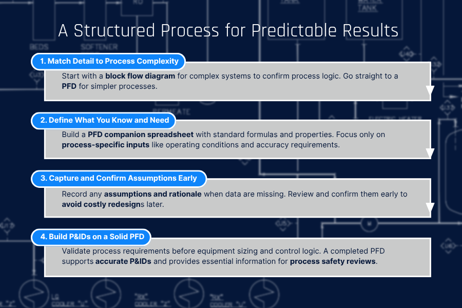
A Structured Process for Better Design Outcomes
When clients need support developing PFDs, a structured approach helps reduce burden while improving quality. Our typical workflow:
- Match Detail to Complexity – Simple processes can go straight to PFD development; complex systems benefit from block flow diagrams first to validate overall process logic.
- Separate What’s Known from What’s Needed – Develop a companion spreadsheet alongside the PFD to define all process flows. Pre-populate it with standard formulas, physical properties, and relationships between parameters—so when one flow is defined, related flows calculate automatically. This allows focus on process-specific inputs like formulations, operating conditions, and required measurement accuracies rather than recreating calculations. The spreadsheet serves as both a design tool and a reference for future modifications.
- Document Assumptions Clearly – Where data aren’t available, document assumptions with supporting rationale. Review with stakeholders and obtain agreement before finalizing the PFD. This prevents discovering sizing errors months into design.
- Use the PFD as the Foundation for P&IDs – When process requirements are validated upfront, equipment sizing, control logic, and instrumentation accuracy are defined correctly the first time. The completed PFD also provides process safety information needed for hazard analyses, ensuring compliance documentation is built on solid engineering rather than guesswork.
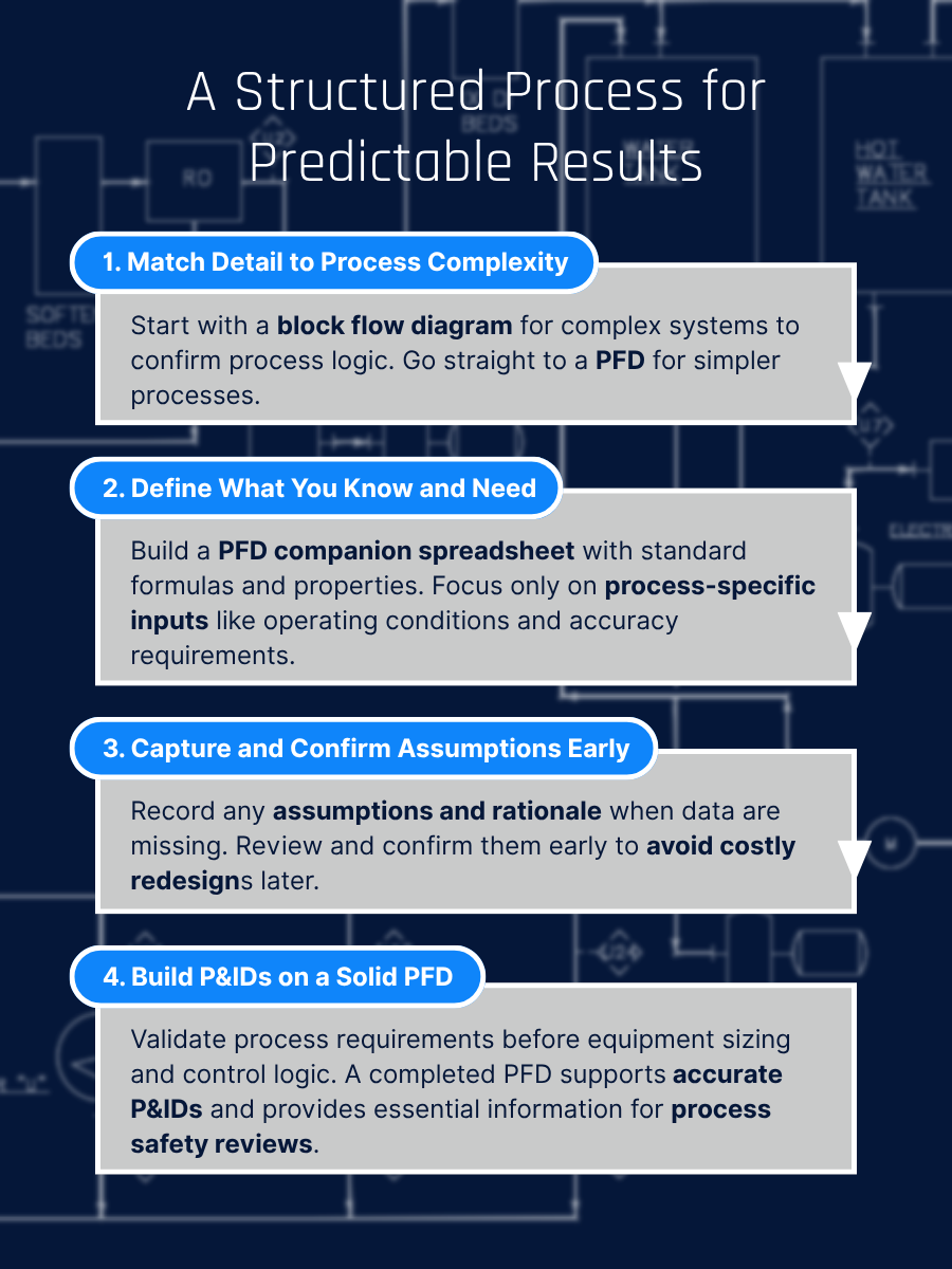
Figure 3. A structured workflow connects process definition to design execution. Following these four steps helps teams create PFDs and P&IDs that reduce rework, improve accuracy, and support predictable project outcomes.
Providing the right information up front allows the design team to move faster and deliver a more complete P&ID earlier in the schedule. Focusing on accuracy supports efficient PSM documentation, which is later used for process hazard analyses (PHA) and management of change (MOC).
Clarity Is the Foundation of Predictable Outcomes
Experience shows time and again that an early focus on developing PFDs and P&IDs the right way is the difference between projects that struggle at all phases and projects that succeed predictably. When PFDs establish solid process foundations and P&IDs accurately translate that intent into buildable systems, installation will go smoothly, startup will happen on schedule, and operations will have the information they need for streamlined process execution. Just as importantly, when modifications or improvements come up years later, that same documentation continues to guide decisions with confidence.
At C-P Systems, we combine process expertise and experience to help clients create documentation that supports predictable, efficient execution. Our disciplined design practices and collaborative approach ensure that every detail contributes to clarity, not complexity. This focus helps manufacturers reduce risk, avoid rework, and build long-term reliability from concept to completion. Explore our Process Engineering services to see how disciplined process design and documentation can improve predictability across your next project.