“As-Designed” ≠ “As-Built”
Much of the “as-built” documentation that we see is simply the final design set. At first glance, it might seem accurate because it reflects what the system does. However, most teams rarely verify these documentation packages after installation and commissioning.
| AS-DESIGNED | AS-BUILT |
Includes all trades installed in a system | X | ✓ |
Accounts for field changes made by contractor during install | X | ✓ |
Captures mobile but necessary items like workstations and equipment staging areas | X | ✓ |
Table 1: The differences between “as-designed” and “as-built.”
Engineers and contractors are not infallible; differences from the designed system to the installation can be introduced for a variety of reasons:
- Overpoured building foundations prevented new equipment pedestals from being installed in the correct position
- Future pipe routes are blocked by undocumented conduit routing or HVAC ducting
- Legacy facility drawings did not show decades of structural modifications and retrofits to the facility
Why Documentation Accuracy Breaks Down Over Time
With everything that goes into installing a new process in your facility, it’s easy for documentation to be treated as an afterthought. The problem lies in updating it across multiple projects, project engineers, designers, engineering firms, and installation contractors. Many facility owners start at a disadvantage: beautiful hand drawings of the original facility from the 1970s are now unreadable scanned images on a computer screen. These artifacts don’t reflect half of what has changed since then. Incomplete P&IDs don’t show recent additions and still show long-since demolished piping. 3D models are missing key details from other disciplines, such as electrical conduit, HVAC ducts, facility piping, lighting, control and electrical panels, or piping supports.
There is perennial intention to update documentation after construction. The reality, though, is that there’s a lot of coordination that goes into installing a new process. By the end of it, most parties are just relieved that it’s complete. When projects are delayed, fast-tracked schedules often shift the focus from documentation updates to startup. Contractors may skip redlines, managers may let them slide, and owners often lack the time and resources to keep documentation fully up to date.
Hidden Costs of Trusting the “As-Built” Documentation
Trusting “as-built” documentation costs you both time and money. Prefabrication can save you thousands in onsite labor costs and reduce change order potential. But if designs are based on inaccurate “as-built” documentation, prefabrication misfits are likely, which would require onsite modification causing schedule delays. And as you plan for the future, process expansions can be boxed out by misplaced equipment that is not accurately represented on drawings, impacting your business’s earning potential. Beyond cost overruns and schedule delays from outdated layout drawings or models, inaccurate “as-built” P&IDs can increase safety risk and compromise compliance to OSHA Process Safety Management (PSM) and other standards.
As field changes accumulate, the gap between the “as-designed” documentation and reality grows. Early deviations from the design during the initial construction can multiply downstream. Even a few inches of deviation can create challenges with other disciplines or prefab assemblies, often leading to costly modifications and delays.

Figure 1. As a project progresses, changes in the installation from the original design have an exponential impact.
In one recent project, our engineer encountered a wall that was 6 inches off from the location on the drawing. This required us to use brackets in order to install a pump in the proper location. These custom brackets cost the customer thousands in additional materials and added weeks of lead time and installation to their timeline; once the discrepancy was identified, additional time was necessary to investigate, verify, review possible solutions and implement them.
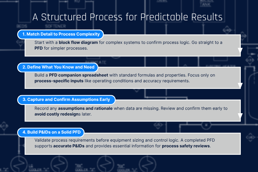
How to Design a Workflow That Prioritizes Accurate Documentation
Accurate documentation doesn’t happen by accident. It requires a deliberate process that starts at project kickoff and continues through installation and startup. At the beginning of a project, set expectations by assessing the current state of your documentation and identifying any missing information. Then, get initial verification in your facility through a targeted walkdown of your P&IDs and other critical areas of your system to see whether the documentation can be trusted or needs deeper review. For a more accurate and complete picture of your space, follow-up your walkdown with a laser scan that captures all disciplines and can easily be integrated into your 3D models. As work on the new project begins, ensure stakeholder alignment by documenting updates from engineering and contractors as they happen. Finally, assemble all updated documentation at the end of the project and mark it “as-built.”
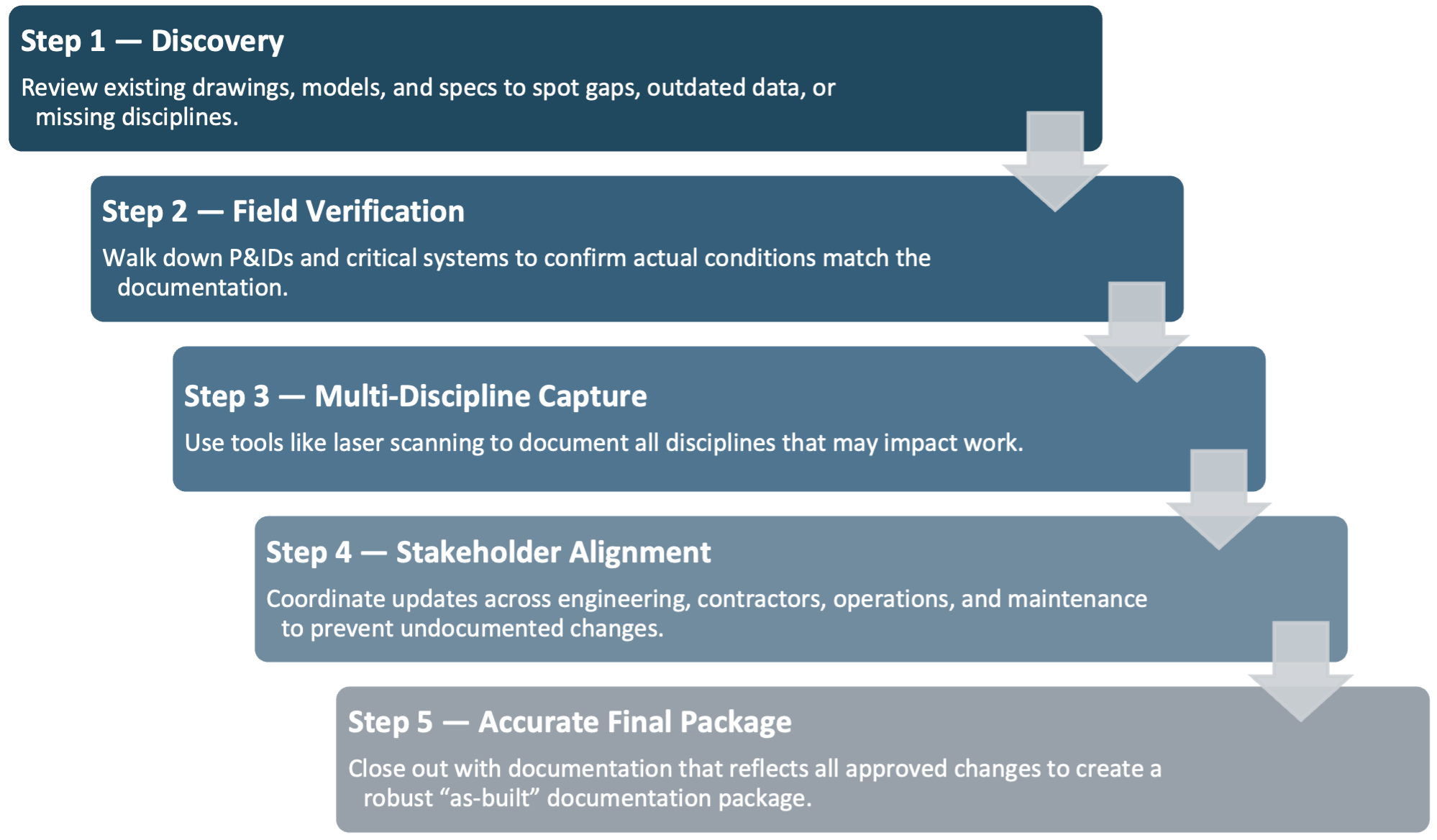
Figure 2. A disciplined workflow that prioritizes up-to-date documentation can improve project accuracy and prevent unexpected consequences.
What You Can Do Today
If you’re concerned that your “as-built” documentation is really “as-designed,” here are three low-effort checks you can do today.
1. Spot-check your existing design with a P&ID walkdown
When planning for process updates or modifications, always budget a line item for validation. A P&ID walkdown does not require special equipment or training.
2. Plan for laser scanning and create a digital twin of your facility
Laser scanning is often the most cost-effective option for accurately capturing measurements and the spatial relationship between disciplines within your facility. They can also be integrated with 3D models to create a contextual digital twin of your process and can be completed in a few days, depending on the process area’s size. Beware, however, that scans are a snapshot in time and are only “as-built” until something is changed in the field. Rather than scanning an entire facility, it is generally more efficient to scan only the area tied to the current project, since future work will often require new scans.
3. Treat each drawing and calculation as living documentation
As your projects progress, create a culture of living-documentation. Ensure that every change in a design—no matter how small—is included in the documentation. Redlining (and the subsequent documentation updates) should be part of your process.
Start With What’s Real, Not What’s Assumed
Accuracy starts with understanding what is real, not what is assumed. When designing a process modification, we can make many assumptions based on material properties, flow rates, etc., but the most expensive assumption is that the documentation is accurate.
“As-designed” and “as-built” are not the same thing. Learn more about how reliable baseline data can help turn complex industrial projects into predictable, efficient installs.