Relief valves
Spring-loaded relief valves are the most widely used type of relief 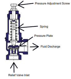 device for pressure vessels and pipelines. The major advantage of these is the ability to close once the pressure inside the protected equipment has dropped a small amount (~3%) below the relief device set pressure. However, the major disadvantage is that mechanical parts of the device can become corroded or clogged and not work as intended (either not opening at the set pressure or fluid leaking through the valve seat below the set pressure).
Set Pressure: The set pressure marked on the relief valve can be no higher than the maximum allowable pressure of the equipment it is protecting. Also, the set pressure should be at least 10% higher than the equipment operating pressure. This avoids valve chatter as the relief valve opens and closes repeatedly. Valve chatter can result in premature failure of the valve seat causing fluid leaks through the valve while closed.
Example:
- Equipment normal operating pressure = 90 psig (6.2 bar)
- Maximum allowable pressure of the equipment = 100 psig (6.9 bar)
- Relief Valve set pressure = 100 psig (6.9 bar)
Size: The size of the relief valve is based on the highest flow rate of all the potential overpressure conditions. Equations for determining required flow area for relief valves are found in API Recommended Practice 520 [1].
Rupture Discs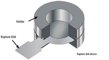
A Rupture disc is a non-reclosing relief device that has the major advantage of being fairly simple with no moving parts. The disc is typically made of a thin metal that is calibrated and tested to fail within a few percent of the specified set pressure. A major disadvantage is that once the disc ruptures as intended, the vessel is open, and the disc and holder must be removed to replace the disc and put the vessel back into service.
Set Pressure: The rupture pressure marked on the disc can be no higher than the maximum allowable pressure of the equipment it is protecting. Also, the disc could fatigue and fail below its marked burst pressure if the actual operating pressure of the equipment is within 10% of the rupture pressure. The rupture pressure of a metal disc is sensitive to temperature, so a temperature is included on the rupture disc tag.
The rupture pressure of the disc is calibrated to the temperature specified by the user since the disc will rupture at a lower pressure as the temperature increases.
Size: As with relief valves, the size of the rupture disc is based on the highest flow rate of all the potential overpressure conditions. Equations for determining required flow area for rupture discs are found in API Recommended Practice 520 [1]. Note that for a given required relief flow rate, a rupture disc may require a smaller pipe size since the flow area of a rupture disc for a given pipe size is greater than the flow area of a spring-loaded relief valve.
Buckling Pin Devices
A buckling pin device is also a non-reclosing relief device. There is a moving plate/piston (similar to a relief valve), but an external mechanism houses a pin which is mechanically linked to the plate/piston. The pin restrains the movement of the plate until the specified set pressure is reached. The main advantage of this type of device is that the pin can be replaced and the device re-set without removing the device or piping from the equipment. As with rupture discs, the process is open to the atmosphere until the pin is replaced.
Set Pressure: The pressure marked on the pin device can be no higher than the maximum allowable pressure of the equipment it is protecting. Advantages of this type of device are that the pin buckling pressure is insensitive to process temperature, and the equipment operating pressure can often be within 5% of the set pressure.
Size: As with relief valves, the size of the pin device is based on the highest flow rate of all the potential overpressure conditions. Equations for determining required flow area are found in API Recommended Practice 520 [1].
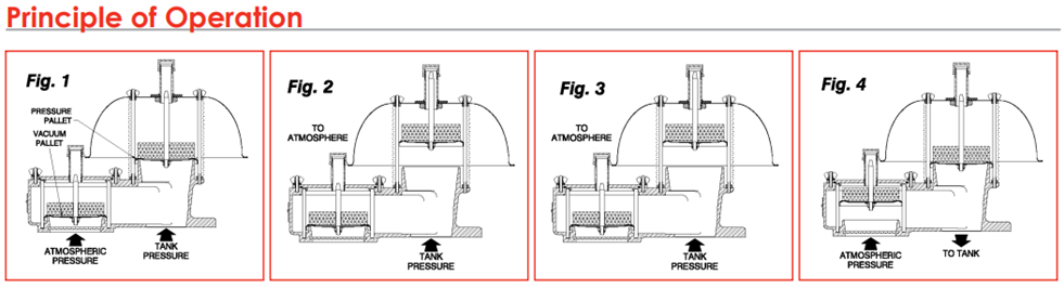
Pressure/Vacuum Vents
Pressure/vacuum vents (also known as conservation vents) are typically used on atmospheric storage tanks that require a set pressure less than 15 psig (1.03 bar). The devices also provide protection against high external pressure that might cause the tank to collapse. The main purpose of pressure/vacuum vents is to let the tank “breathe” by allowing air in and out as the tank is heated/cooled by the atmosphere, and when liquid is pumped in or drawn out. The device operates by means of a weighted plate or spring that is calibrated to lift off the seat at a specified internal positive pressure or a second plate/spring calibrated to lift at a specified external pressure.
Set Pressure: The set pressure can range from 0.5 oz/sq in (0.0022 bar) to up to 12 oz/sq in (0.052 bar). Spring loaded types can be set for up to 15 psig (1.03 bar). Vacuum settings can range from 0.5 oz/sq in (0.0022 bar) to 12 oz/sq in (0.052 bar).
Size: As with other types of relief devices, the size is based on the highest flow rate of all the potential overpressure conditions. For atmospheric tanks, a combination of multiple overpressure scenarios must be considered simultaneously. Rules and equations for determining required flow area are found in API Standard 2000 [2].
In addition, a fire surrounding the atmospheric tank must also be considered as a potential overpressure scenario. API 2000 has equations for this scenario as well. This scenario usually results in a much larger required relief size than normal in-breathing and out-breathing mitigated by a pressure/vacuum vent. Emergency relief manways are often installed to protect against this scenario. The set pressure on an emergency relief manway is typically set higher than the pressure/vacuum vent if both devices are installed on an atmospheric tank.
__________
[1] API 520, Sizing, Selection and Installation of Pressure-Relieving Devices in Refineries, Webstore | Standards (apiwebstore.org)
[2] API 2000, Venting Atmospheric and Low Pressure Storage Tanks, Standards (apiwebstore.org)