C-P Systems
Modern Piping Design for Industrial Manufacturing: A Complete Overview
Piping design is at the core of every successful industrial manufacturing project. Learn what effective piping design involves, how modern tools improve outcomes, and why safety, compliance, and efficiency rely on getting the details right from the start of the project.
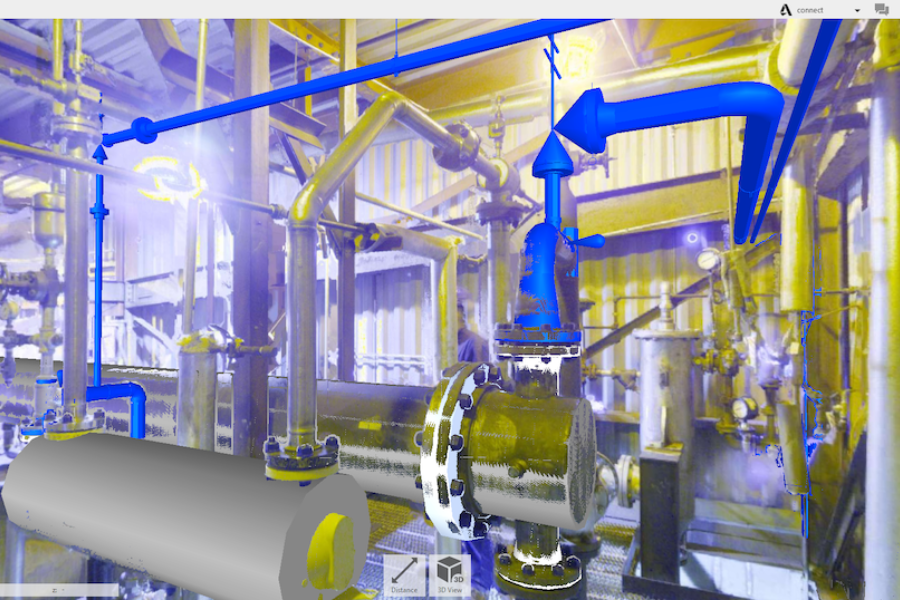
Table of Contents
Piping design is at the core of every successful industrial manufacturing project. It translates process intent into physical reality, ensuring that fluids and gases move through a facility safely, efficiently, and in full compliance with relevant codes. More than just routing pipe in Computer-Aided Design software (CAD), piping design services today must balance constructability, operational access, and long-term maintainability. This is especially critical in industrial manufacturing plants where every connection matters.
Getting it right means more than laying out pipe in CAD. It requires an understanding of operating conditions, material compatibility, industry codes, and the field constraints that influence how and whether your system can actually be built.
In this guide, we’ll explore what effective piping design involves, how modern tools and best practices improve outcomes, and why safety, compliance, and efficiency depend on getting the details right from the start.
Read on, or download the full guide.
Piping Design vs. Piping Engineering
While often used interchangeably, piping design and piping engineering are distinct disciplines that must work in tandem to ensure project success.
Piping Design is focused on the physical layout, routing, and arrangement of pipes, fittings, instruments, and valves within the constraints of the plant environment. Designers develop 3D models, extract isometric spool drawings, and coordinate spatial conflicts to ensure the system is buildable and maintainable.
Think: “Can it be built? Will it fit? Can it be maintained?”
Piping Engineering addresses the technical underpinnings of that design. Engineers handle stress analysis, wall thickness calculations, support spacing, material selection, and compliance with piping codes like ASME B31.3.
Think: “Will it work? Is it code compliant? Will it hold up under pressure and temperature?”
The integration between piping design and piping engineering is critical. A good design layout means nothing if the system can’t hold up mechanically. Even perfect calculations fail if the piping can’t be installed or accessed in the field.
History of Piping Design
Piping design has changed dramatically over the past few decades, from plastic models and vellum drawings to fully integrated 3D design environments. Each era brought gains in accuracy and efficiency, but also tradeoffs in how teams visualize space and ensure constructability. This progression isn’t just theoretical. It reflects real shifts in how projects are delivered, reviewed, and built. Teams that have experienced these transitions firsthand bring a deeper understanding of what works and what still fails in modern design.
Era | Tools & Limitations |
1950s–1970s | Manual drafting, mylar overlays, scale models |
1980s–1990s | 2D CAD introduced faster drafting but lacked modern meta data intelligence |
2000s–2010s | 3D CAD with some specification integration and clash detection |
2010’s Present | Spec-driven 3D platforms, laser scan integration, automated deliverables |
Today’s platforms enforce line class consistency, automate isometric and Bill of Materials (BOM) generation, and integrate laser scan data directly into design models. This not only speeds up drawing production but reduces the risk of mismatches between intent and install. The result is tighter coordination, fewer Requests for Information (RFIs), and piping packages that reflect reality from day one.
👉 Read more: The Evolution of Piping Design Our full blog post explores how these changes unfolded firsthand. It spans from the plastic model era through early AutoCAD adoption, and what younger designers often miss when they rely too heavily on software.
Why Piping Design Matters
Piping design is where engineering process intent meets physical reality. It’s not just about connecting equipment. It’s about doing so in a way that ensures performance, safety, maintainability, and cost-efficiency over the full lifecycle of a system.
When done well, piping design creates systems that are:
- Safe: Routed to prevent hazards, equipped with the right pressure relief and compliant with relevant codes
- Efficient: Designed to reduce pressure drop, minimize unnecessary fittings, and optimize flow paths
- Maintainable: Accessible for operators and mechanics, with space for draining, isolating, and servicing critical components
- Constructible: Delivered with clean isometric drawings, BOMs, and spool documentation that enable accurate fabrication and field install
These tools aren’t just about automation. They help catch problems early and reduce surprises in the field. They help teams resolve spec mismatches before procurement, spot layout issues that complicate installation, and catch instrument or valve selections that don’t align with field conditions.
Thoughtful piping design anticipates future realities. It incorporates lessons from real installations and field walkthroughs. The best designs consider not just what works in the model, but what holds up in operation and maintenance over time. They’re not just technically correct; they’re built with an understanding of how systems will be installed, operated, and serviced 5 or 10 years from now.
Smart 3D piping design prevents:
- Surprise RFIs and rework in the field
- Inefficiencies caused by overly complex routing
- Long-term reliability risks from underspecified materials
- Regulatory issues stemming from noncompliant tie-ins
Piping design isn’t a back-office drafting task. It’s a critical project deliverable that protects your timeline, your operators, and your plant.
How Industrial Piping Design Takes Shape
Piping design doesn’t begin in a 3D model. It begins with understanding how a facility is meant to function. Every line you see on a spool drawing can be traced back to upstream decisions: process intent, control logic, material compatibility, and layout constraints. Good piping design connects these decisions with precision.
The process typically unfolds in stages:
- Process Flow Diagrams (PFDs) outline major equipment and material movement. They set the stage for the system’s purpose and sequence but don’t yet show the complexity behind control, safety, or tie-ins.
- Piping & Instrumentation Diagrams (P&IDs) bring in system logic: valves, instruments, reliefs, and line numbers. These diagrams carry legal and regulatory weight, and they’re only as effective as the software and version control behind them.
👉 Read more: Choosing the Right P&ID Software
- Line classes and specifications define the materials, wall thicknesses, gaskets, valve trims, and connection types for each line: creating the rules that the model must follow.
- Laser scanning captures field conditions with precision, providing a trusted spatial reference for routing tie-ins, locating supports, and verifying clearances. Armed with a laser scan, you can model with confidence and deliver predictable, surprise-free outcomes during installation.
- Spec-driven 3D modeling transforms logic into layout, placing lines into real plant space while resolving clashes, elevation shifts, and field constraints.
- Deliverables emerge from the model: isometrics, BOMs, demo plans, tie-in scopes, and tagged valve and instrument lists. Each one anchored in the earlier stages of design.
What starts as a few boxes on a PFD becomes a complete piping system if the right foundation is laid. Rushing one step, skipping a review, or managing specs loosely can lead to costly rework, missed compliance issues, or field surprises.
Well-run projects don’t just have good models. They have a solid design path that connects process to plant.
Modern Tools That Improve Accuracy and Speed
Piping design depends on more than technical know-how. It also requires digital tools that bridge design intent with real-world execution. Whether you’re working in 2D, 3D, or integrating both, the right software helps translate process into piping that actually works in the field.
We use several platforms depending on project scope and client needs, but this is just a sample. There are many tools available; what matters most is how they’re selected and applied.
- AutoCAD Plant 3D: A widely adopted platform that balances capability with flexibility. It supports spec-driven 3D modeling, automatic isometric generation, and coordination with laser scan point clouds. This makes it ideal for retrofit projects or teams that want intelligent design without the overhead of a full plant model.
- Smart 3D (Hexagon) and AVEVA E3D: These enterprise-level systems are designed to model entire facilities within a unified environment. Think of them as the industrial-grade toolbox of plant modeling: powerful, integrated, and highly structured. They offer deep functionality, but demand strong administrative oversight, licensing investment, and consistent internal standards to fully realize their value. For teams focused on a single process area or isolated system, the overhead of managing these platforms may outweigh the benefits.
- 2D Drafting Tools: Still indispensable in the right context. 2D tools allow experienced designers to produce fabrication-ready views with detailed annotations, BOM callouts, and installation notes. They often provide more precision and customization than a 3D model permits. While 3D is the norm for layout, 2D remains unmatched for clarity in certain deliverables.
Coordination & Review Tools
- Navisworks: Often misunderstood as a design platform, Navisworks is a model aggregator that supports clash detection and review across disciplines. It also includes a free viewer that makes it accessible to project managers, construction teams, and plant personnel. Compared to raw scan data or native design files, its compact size and simple interface make coordination much easier.
- Document Management Tools: Dedicated document control systems are critical to support version control, approval workflows, and traceability throughout the project lifecycle.
The Role of Specifications in Piping Design
Piping specifications are the foundation for consistent, safe, and constructible design. More than just material callouts, they serve as a shared language across engineering, procurement, and construction to ensure every component in a piping system fits, functions, and complies with project requirements.
At their core, specifications define:
- Pipe material and wall thickness
- Flange class and connection types
- Valve trim and gasket compatibility
- Testing standards and fabrication rules
Want a closer look at how to read and apply a piping spec?
👉 Check out our post on decoding piping specifications
But their role goes far beyond definition. In modern design environments, specifications are embedded into 3D platforms and validated automatically. Designers are guided by pre-built spec libraries, helping catch mismatches like incompatible weld schedules or incorrect gasket ratings before drawings are even issued. This reduces the burden on QA reviews and helps avoid confusion in the field.
Without spec enforcement, common risks include:
- Material mismatches that lead to failure or accelerated wear
- Procurement delays caused by unclear or inconsistent requirements
- Field improvisation when incompatible components arrive on-site
- Costly rework due to errors discovered after fabrication or install
- Process safety incidents due to incompatible materials or mismatches with process conditions
These issues aren’t just theoretical. They’re frequent culprits in project overruns. That’s why spec-driven design is a best practice, not a luxury.
The Role of Laser Scanning in Piping Design
Laser scanning captures precise, as-built measurements of existing facilities using high-resolution 3D point clouds. For brownfield or retrofit projects where documentation is outdated, inaccurate, or incomplete, laser scanning gives piping designers a trusted spatial reference to model tie-ins, locate supports, and verify field constraints.
Traditional field measurement methods can be slow, labor-intensive, and prone to human error. Laser scanning replaces that guesswork with accurate, detailed data, even in hard-to-access areas. This reduces the need for return site visits or manual modeling.
What makes laser scanning effective isn’t just the technology, it’s how it’s applied. The most valuable scans aren’t the most exhaustive; they’re the ones that capture exactly what’s needed for design, fabrication, and install. That’s why experienced piping designers who understand what matters downstream are best equipped to lead the scanning effort.
Well-integrated laser scans support:
- Accurate tie-in planning: Capturing the real location, elevation, and orientation of existing piping
- Efficient layout: Avoid spatial conflicts by integrating scan data into design software for review of routing through congested areas before any piping is installed
- Better field outcomes: Reducing RFIs, rework, and install surprises
Even minor dimensional discrepancies can cause major installation issues. A well-executed laser scan ensures your model matches field reality. This gives you confidence in every spool, support, and weld point.
Learn how 3D laser scanning enables offsite piping prefabrication in our white paper Laying the Foundation for Industrial Project Success.
What to Watch For: Common Piping Design Mistakes
Avoiding field chaos starts with better design that goes beyond just routing pipe in a model. Some of the most critical errors we see in the field stem from overlooked details or incorrect assumptions and mistakes early in the piping design process:
- Overlooking field conditions: Designs that ignore as-built constraints or real tie-in locations often need to be redone on-site.
- Delaying stakeholder input: Waiting too long to involve operations, maintenance, or engineering staff can result in late-stage changes that compromise cost and schedule.
- Skipping foundational steps: Jumping into 3D modeling without first establishing a clear process flow, accurate P&IDs, and verified field conditions often leads to misalignment and rework.
- Focusing only on design intent: Failing to consider constructability, ergonomics, and long-term access creates avoidable problems for installers and operators.
- Designing too late in the project: When piping design begins during or after construction planning, it’s often reduced to firefighting: solving immediate problems instead of preventing them. Trying to design while building eliminates the opportunity for strategic layout, cost savings, and constructibility planning.
- Assuming CAD is reality: Modeling piping into spaces and placements that don’t actually exist due to outdated scans or reliance on as-builts leads to field improvisation and rework.
These issues tend to compound over time. A rushed or incomplete foundation leads to modeling gaps. Missed reviews lead to missed constraints. All of it shows up in the field when changes are most expensive.
Avoiding these mistakes isn’t about being perfect but about following a structured process with the right checks at the right time. That process only works when it starts early. Done early, piping design prevents costly field improvisation. Done late, it becomes expensive damage control. When applied correctly and at the right phase, piping design pays for itself and then some.
Piping design isn’t just about getting the model right. It’s about making sure the real-world system can be built, accessed, and maintained without surprises.
Explore our deeper dive on this topic:
👉 Common Piping Design Mistakes (and How to Avoid Them)
Bridging Design and Construction
The real value of piping design isn’t just in how a system looks on screen. It’s in how reliably it installs in the field. The best designs don’t just meet code or fit in the model; they anticipate how piping will be fabricated, lifted, bolted, supported, and accessed.
Problems that show up during construction often trace back to decisions made early in design. When tie-in scopes are vague, spool breaks are overlooked, or bolt access isn’t considered, installers are left to improvise and project costs start to rise.
A field-driven design process accounts for these realities:
- Spool-level detail: Breaks defined where fabrication and transport make sense
- Install access: Space for rigging, bolt-up, insulation, and long-term maintenance
- Clear documentation: Isometrics, cut plans, and tie-in details that leave no room for interpretation
These aren’t just design details. They’re what reduce uncertainty during construction. Clear, buildable documentation leads to cleaner bids, fewer assumptions, and fewer surprises in the field.
Want a deeper look at how these principles play out in practice?
👉 Read our blog on what makes piping design constructible
Codes, Standards, and Compliance
Piping systems don’t just need to work. They need to meet the safety, reliability, and documentation expectations of both your facility and external authorities. But compliance isn’t always as simple as following a specific code. Many facilities struggle with inconsistent standards, fragmented documentation, and internal silos where different departments or sites use conflicting specs, naming conventions, or review processes.
The goal isn’t just technical compliance but consistency. A strong design process ties together site-specific piping specs, corporate design standards, and the right external codes to ensure every system is documented, reviewable, and safe to operate.
We commonly work with the following standards, depending on service, client requirements, and local jurisdiction:
- ASME B31.3 – Process piping
- OSHA PSM – Process Safety Management for covered chemicals and mechanical integrity
- API 520/521 – Relief valve sizing and overpressure protection
- NFPA 30 – Flammable and combustible liquids
What matters most is not just what codes apply, but how they’re interpreted, documented, and implemented consistently across your team.
Choosing the Right Piping Design Partner
Not all piping design firms operate the same way, and the differences don’t always show up in a proposal. A low bid might look appealing, but the real cost shows up later: rework, delays, unexpected change orders, and systems that don’t perform as expected in the field.
Choosing the right partner is less about features and more about fit. You need a team that understands your plant’s standards, communicates clearly, and delivers design packages that can be built, maintained, and trusted.
We’ve developed a detailed checklist to help plant managers, project engineers, and procurement teams make that decision.
👉 Download the checklist: What to Ask Before You Commit
Here’s a preview of what to consider:
What to Look For | Why It Matters |
Process and piping specialization | Firms that treat piping design as a primary focus—not an afterthought—are more likely to understand constructability, operability, and field constraints. |
Experience in your industry | Compliance with ASME, API, OSHA PSM, and NFPA standards requires both knowledge and judgment—especially in high-risk process environments. |
Field-aware design | Strong design packages anticipate install needs: spool breaks, access for rigging and maintenance, and tie-in clarity. |
Spec-driven tools and documentation | Design software should enforce line classes, generate BOMs/isometrics, and ensure specs are carried through to fabrication. |
Version control and document management | Projects succeed or fail on communication. Document management for structured workflows prevents errors due to outdated drawings or unclear responsibilities. |
Alignment with plant standards | Your design partner should integrate seamlessly into your naming conventions, layer structures, and procedural workflows—not create silos. |
Piping design isn't just a technical service. It's a chain of decisions that affects every downstream step. The right partner helps you move from concept to construction with fewer surprises and more confidence in the outcome.Shape
Conclusion & Next Steps
Strong piping design services do more than produce drawings. They deliver constructible, maintainable, and code-compliant systems with fewer surprises. From early process definition to final spool drawings, C-P Systems supports industrial manufacturing plants with a design approach grounded in real-world execution.
If you’re looking for piping design services for chemical plants or other process-driven facilities, we’d love to learn more about your project and share how we can help.
→ Schedule a free consultation
→ Download our checklist: What to Ask Before You Commit
→ Contact us to start a proposal
Let’s make your next project more predictable, from first draft to final bolt-up.
External Resources and Reference Links
The following reference sites, tools, and handbooks provide additional insight, technical detail, and real-world guidance that align with C-P Systems’ approach to piping design:
Piping Design and Component References
- Wermac.org – Piping symbols, valve types, dimensional standards, and pressure ratings
- Cole-Parmer Chemical Resistance Guide – Compatibility of piping materials with process fluids
- Fusion Fluid Equipment Calculator – Mixing and tank volume calculators for sizing and flow planning
- The Engineering Toolbox – Tools and calculators for engineering and design applications
Codes and Standards
- ASME B31 Code Overview – Process and power piping design standards
- NFPA Codes and Standards Directory – Relevant fire and safety guidelines including:
- NFPA 30: Flammable and Combustible Liquids
- NFPA 55: Compressed Gases and Cryogenics
- NFPA 69: Explosion Prevention Systems
Software Platforms and Documentation
- Autodesk Plant 3D – Spec-driven 3D piping design and isometric generation
- Hexagon Smart 3D – High-end 3D modeling and project integration tools
- Navisworks – Model aggregation, clash detection, and multi-discipline review
- AVEVA E3D – Advanced design platform for complex and brownfield systems
Recommended Handbooks
- Piping Handbook by Mohinder L. Nayyar – In-depth engineering reference for pipe specifications, materials, and layout standards
- Perry’s Chemical Engineers’ Handbook – Foundational text for process engineering, fluid dynamics, and system integration
Download the Full Guide
About C-P Systems
SETTING THE STANDARD FOR CHEMICAL ENGINEERING FIRMS EVERYWHERE
Through unmatched professionalism, knowledge and experience, we set the industry bar for chemical engineering firms. With decades of chemical plant engineering and piping design experience, our team of licensed engineers can handle any project scope.