A Piping and Instrumentation Diagram (P&ID) often first appears to a non-engineer in a meeting, when someone places the drawing on a screen and begins pointing. The discussion may concern a project kickoff, a proposed upgrade, or a line that keeps tripping. A reader does not need to know how to create the drawing. The practical goal is to follow the discussion, ask useful questions, and judge whether the P&ID is current and reliable.
This article explains what a P&ID is, how a first-time reader can get oriented, five elements worth recognizing, how to assess the drawing’s quality, and why it matters outside engineering. Mark Spitzmueller, president and principal designer at C-P Systems, has worked with P&IDs since 1993. The explanations below draw on his experience.
What a P&ID Shows
“The P&ID is the blueprint of a process system,” Spitzmueller says. “It shows every aspect, every feature critical to the operation and maintenance of a system.”
In practical terms, a P&ID is a schematic that shows process equipment, the piping connections between equipment items, valves, instruments, and control functions. It represents process relationships rather than exact routing, dimensions, or every pipe fitting. Major equipment, instruments, and tagged valves carry unique identifiers. Depending on the item, that identifier also appears in the corresponding equipment, instrument, or valve list and on an attached physical identification tag when one is specified.
A P&ID shows how a system functions and connects. A layout drawing shows where equipment and piping sit within the facility. Two vessels drawn side by side on a P&ID may be on different floors because the schematic represents process relationships and flow rather than physical location.
P&IDs generally follow block flow diagrams and process flow diagrams (PFDs) as the design develops. A block flow diagram shows the major process steps as boxes, while a PFD adds the principal equipment and process streams. A P&ID adds the piping, line identifiers, valves, instruments, control functions, and other details needed to define how the system operates. Spitzmueller describes it as the combination of a mechanical flow diagram, which covers piping and valves, and an instrumentation diagram, which covers controls.
Start with the Legend
A complete P&ID set should include a legend sheet that defines the symbols and abbreviations used throughout the drawings. Depending on the project, the legend may cover equipment and valve symbols; line types for primary process, secondary, future, jacketed, and double-contained piping; instrument symbols and identification letters; line-number structure; off-page connectors; and service codes that identify line contents, such as nitrogen.
Review the legend before reading the remaining sheets and keep it available. The legend answers many questions that may arise for a first-time reader.
Many process companies base their P&ID requirements on practices published by Process Industry Practices (PIP), a consortium founded in 1993 to harmonize engineering practices across owner and contractor organizations. PIP PIC001 defines requirements for P&ID format and content. Companies typically supplement that baseline with owner-specific symbols, service codes, and project requirements. When a facility has no drawing standard or must replace inconsistent legacy drawings, adopting a recognized practice gives engineers and contractors a common documentation baseline.
Five Things to Learn to Recognize
Five elements give a first-time reader the most useful starting point.
Equipment Symbols
Common equipment types, including pumps, tanks, reactors, heat exchangers, and columns, use recognizable symbols defined on the legend. Identifying the major equipment makes it easier to follow the process from item to item. Modern redraws often spread a system across more sheets than older hand-drawn P&IDs to improve legibility.
Valve and Instrument Symbols
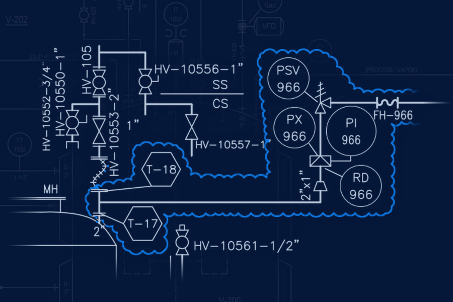
Valves appear as symbols on process lines, and the legend distinguishes manual, control, relief, and other valve types. Instruments and control functions often appear inside circles, commonly called bubbles, with identifying letters and a loop number. ANSI/ISA-5.1 provides the widely used identification convention. The first letter identifies the measured or initiating variable, such as F for flow, P for pressure, T for temperature, or L for level. Succeeding letters identify functions, such as I for indicate, T for transmit, or C for control. FT-101 identifies a flow transmitter in loop 101. Lines and other variations in an instrument symbol indicate location, accessibility, or function according to the legend. A reader should use the project legend rather than assume every organization applies the symbols identically.
Line Tags
Each process line should carry an identifier that follows the project’s line-numbering convention. A typical identifier may include the area or unit, service, sequence number, nominal pipe size, piping class or specification, and insulation or tracing designation. The exact order and fields vary by owner. Once the convention is understood, a reader can identify the line service, nominal size, and applicable piping specification.
Flow Direction
Arrows indicate the direction of process flow. Reading the drawing begins with following each stream from its entry point to its exit point. Without clear flow arrows, the relationship between upstream and downstream equipment becomes ambiguous.
Off-Page Connectors
A process system rarely fits on one sheet. An off-page connector marks where a line continues and references the source or destination drawing. The matching connector allows a reader to trace the same line or stream across the P&ID set.
How to Assess P&ID Quality
A reliable P&ID is accurate, complete, legible, and current. A complete drawing shows all equipment, piping, valves, instruments, control functions, line identifiers, and flow direction required by the project standard. A legible drawing can be read without unnecessary effort. Older hand-drawn P&IDs sometimes compress a large system into only a few sheets, making them difficult to use.
Accuracy cannot be confirmed from a desk alone. Field verification requires a walkdown that traces each line and records the equipment and components that belong on the P&ID, along with materials of construction, nominal sizes, and relevant configuration details. Laser scanning can capture the geometry of an existing area for 3D modeling, but it does not identify every component, material, or process function and does not replace the walkdown.
Spitzmueller uses an analogy to explain why a missing item on the drawing matters. “It’s just like if you’re building a house. If the windows aren’t dimensioned, somebody has to guess.” A carpenter working from a plan without a window will not frame one. The same rule applies to a valve. “If the valve isn’t shown when we’re doing our process or piping design, we’re not going to put in flanges, bolts, gaskets. It’s not going to appear. It’s not going to be in the system.” If that valve was the isolation valve a crew needs to shut the line down for maintenance or in an emergency, the plant now has a gap where it should be.
That is also why walkdowns are a standard part of the work. Before a design goes out, and often when engineers pick up an existing facility, they walk the physical system against the P&ID line by line, confirming that every valve, instrument, and connection on the drawing exists in the field, and that everything in the field appears on the drawing. The P&ID is the source of truth, and the walkdown is how it earns that status.
His shorter version: “If it’s not on the P&ID, it’s not in the system.”
Why P&IDs Matter Outside Engineering
Non-engineers usually encounter a P&ID during a meeting or while investigating a problem.
In a meeting, the P&ID serves as the shared technical reference. Project planning, proposed upgrades, and operations issues all begin with the system’s current configuration. The team uses the P&ID set to identify where work will occur and how a proposed change connects to the existing process. During a plant upset or when a line keeps tripping, the team uses a current P&ID to understand the installed system and evaluate options.
At plants without current P&IDs, Spitzmueller often sees the same pattern: detailed knowledge of the system rests with one or two experienced employees. “Who knows the system? Joe does. Bring Joe out there. He’ll show you where that valve is,” he says, describing a response he frequently encounters in the field. Questions route through one person, training depends on that person’s availability and memory, and critical information may leave when that employee retires or moves on. A current P&ID captures that knowledge in a shared, controlled record that operations, maintenance, and engineering can verify and use consistently. Institutional knowledge is valuable, but it is not a reliable substitute for current documentation.
That need for documented process information is also reflected in federal safety requirements. For processes covered by OSHA’s Process Safety Management of Highly Hazardous Chemicals standard (29 CFR 1910.119), P&IDs are required process safety information. The associated process hazard analysis must be updated and revalidated at least every five years. For processes outside PSM coverage, current P&IDs still support maintenance planning, engineering review, management of change, and, in Spitzmueller’s words, “most importantly, the safe operation of a process system.”
In Spitzmueller’s experience, many plants follow a similar pattern. An engineer explains that the P&IDs are out of date and requests funding to update them. The manager agrees it is a good idea and asks for a quote. The quote comes back, and the answer becomes a version of: we have operated this long without it. The drawings get updated when the next upgrade forces the issue.
Deferring the update shifts the cost rather than eliminating it. Any engineering firm asked to modify the system needs accurate P&IDs. If the owner cannot confirm that the drawings match the installed system, the project scope must include a verification walkdown. The plant then pays for the deferred update as part of the next project while carrying unresolved financial and safety risk in the meantime.
What Non-Engineers Need to Know
Non-engineers do not need to interpret every instrument bubble. “It’s not necessarily that they have to fully understand the P&ID,” Spitzmueller says. “They just have to have a certain, for lack of a better term, reverence and trust in the people that do fully understand the P&IDs.”
Treat the current P&ID as a controlled record of the process configuration and the functions it depicts. When the drawing is out of date, take the issue seriously. Project estimates, hazard reviews, maintenance planning, and operator training all depend on accurate process information.
Spitzmueller spent the first three years of his career working on P&IDs before moving into equipment and process design. He still describes P&ID work as a foundational skill for a piping designer. “It’s one of the most critical aspects of what we do,” he says.