The first pump you pick is almost never the pump that ships. Here is why process equipment selection is a chain reaction, and what it costs when one link is wrong. In this article, we dive into how heat exchangers, pumps, valves, reactors, and pressure vessels are specified for industrial process systems.
Process equipment selection is iterative by design. The first pump, valve, or exchanger is a budgetary starting point, sized against preliminary assumptions. As the layout, process parameters, maintenance requirements, and operating cases come into focus, the specification is refined to match. Refining a choice downward is straightforward; sizing back up often is not, which is why early specificity matters.
A heat exchanger with 10 psi of pressure drop instead of 5 changes the pump selection, and a longer piping run adds friction losses that change it again. A control valve that looked sound at the normal operating point may not have enough pressure available at maximum flow. By the time the package is finalized, the equipment reflects the system as it will actually run rather than the first estimate.
A pump interacts with the piping, the control valves, the exchangers, and the vessel it feeds, and one change can reach upstream, downstream, or both. Resolving those interactions is the work of the process flow diagram (PFD), where minimum and maximum rates, operating pressures and temperatures, future capacity, and expected process conditions are pinned down with enough detail to support every selection. Vague numbers on a PFD leave room for rework, resizing, and layout problems that cost far more to correct after installation.
Defining the process precisely up front, with appropriate safety factors, protects the schedule and keeps scope from expanding beyond what the project requires.
Heat Exchangers
The two main types in a typical industrial plant are shell-and-tube and plate-and-frame, and the application determines which one fits.
A phase change in the process fluid, such as condensing steam, is better suited to a shell-and-tube exchanger. Two liquid streams exchanging heat are a more natural fit for plate-and-frame. Cleaning access is another key differentiator. Plate-and-frame exchangers can be fully disassembled, with plates swapped out and both sides cleaned. Shell-and-tube exchangers allow access to the tubes by removing one head, but the shell side is harder to reach. If the shell side needs regular cleaning, that typically means building in clean-in-place (CIP) infrastructure, or requiring a removable tube bundle.
Fouling is the most common field issue. Deposits from the process stream will eventually foul the exchanger, and that reduces heat transfer. The fouling type needs to be identified during design so the cleaning strategy, whether CIP or physical disassembly, can be built into the system. That includes the CIP piping and connections, or the physical clearance around the unit to pull it apart for maintenance.
Fluid properties drive the rest of the selection. Viscosity affects turbulence within the exchanger, which in turn affects heat transfer performance. Suspended solids and entrained gas both change the picture again, and each one narrows which exchanger configurations will work. The fluid dynamics of the process stream must be evaluated to select a configuration that delivers the required heat transfer.
One pitfall worth noting involves condensing steam. At low loading, steam pressure may not be sufficient to push condensate out of the exchanger. The exchanger floods, the condensate becomes subcooled by the process, and when enough pressure finally builds, cold condensate gets pushed into a hot condensate header. The result is loud, violent water hammer. Recognizing that a stall condition will occur at low loads and installing a condensate pump to keep the exchanger from flooding avoids the problem entirely.
Whether a heat exchanger falls under ASME code comes down to size. If the width, height, or cross-sectional diagonal dimension is greater than 6 inches, the exchanger is considered an ASME code vessel. Below 6 inches, it is not.
Pumps
Pump selection starts with the required flow and pressure, though the initial selection seldom survives the downstream design unchanged. An initial assumption about available supply pressure may hold through early equipment selection, only to change as the subsequent design reveals higher pressure losses or a different plant layout than expected. The pump selection adjusts, and that adjustment may ripple through other equipment.
Viscosity is the primary factor dividing centrifugal pumps from positive displacement pumps. A very viscous fluid will not pump well with a centrifugal pump. The process control strategy also matters. If flow is controlled by throttling a valve, a positive displacement pump is not an option because its flow cannot be throttled that way. If pump speed is manipulated instead, different pump types may apply. Choosing one approach may preclude the other.
Undersized pumps present obvious symptoms: a valve running wide open without enough flow, or a pump operating too far out on its curve, which creates reliability problems. Oversized pumps are more insidious. A pump may appear to work fine for years, but examine the actual operating point and it sits too far back on the curve, generating excessive pressure on the impeller and wasting energy. A much smaller pump could do the same job more efficiently and more reliably.
Efficiency ratings alone do not settle energy consumption. A hypothetical perfectly efficient pump that generates 100 psig for a process that only requires 30 psig would consume more energy than an inefficient pump matched to the actual requirement.
The field version of this shows up regularly: a pump producing 60 psi followed immediately by a globe valve throttling 30 psi back out. The margin gets added at the pump and taken back out immediately downstream. It reads as playing it safe, but the margin is paid for twice, once in the capital cost of the larger pump and again in the energy bill for the life of the system.
For critical services where downtime carries significant consequences, redundant pumps with a primary and backup configuration are sometimes warranted. The process risk determines whether that investment is justified.
Under-capacity can also snowball. If a pump is at its capacity limit and a bigger pump is needed, that may require a bigger motor. If the electrical infrastructure does not support the larger motor, the scope grows quickly. Detailed hydraulic analysis, capturing all the pressure losses in the actual plant layout and piping, is what prevents that cascade.
The following example shows how a sound fix can run into an unexpected limit. A pump was constraining the overall process, so a larger impeller was installed. That was the right move, and the motor had the rated capacity to support it. The variable frequency drive, though, kept tripping at power demand levels below what the motor should have handled. The motor was fan-cooled, so the drive derated its capacity at reduced speed to account for the reduced cooling. Exceeding a motor’s capacity by increasing impeller size is a familiar consideration, but this motor would have handled the change if not for that protective feature in the drive. The fix was to back the impeller off part way, still larger than the original but smaller than the first attempt. At the higher speed that allowed, the derate cleared and the capacity gain held. The alternative would have been a much larger investment: a new motor, a long cable run, and a larger drive.
Code and Non-Code Vessels
Whether a vessel is built to ASME code or not comes down to one number: 15 psi. If the maximum allowable working pressure exceeds 15 psi, it is an ASME code vessel governed by ASME Section VIII. Below 15 psi, it is a non-code vessel.
In practice, reactions, mixed vessels, and anything operating with a steam jacket or cooling jacket are typically code vessels. Non-code vessels tend to be atmospheric storage tanks that are not expected to operate near the 15 psi threshold.
The distinction carries specific requirements. All ASME Section VIII vessels require overpressure protection by system design or pressure relief valves, and those relief valves must themselves be ASME code rated. Non-code vessels have fewer relief requirements, but that does not mean they can be ignored. All relief scenarios still need to be covered, and non-code vessels have different overpressure tolerances that must be accounted for.
Vacuum gets less attention. Steam takes up roughly 1,700 times the volume of water. If steam in a vessel condenses rapidly, whether from cold water contact, pumping the vessel contents out, or hot vapors meeting cold rain, the sudden volume reduction can create enough external pressure to collapse the vessel. Vacuum breakers are the standard protection against implosion.
Operating pressure should always maintain an appropriate gap below the maximum allowable working pressure (MAWP). Relief devices have their own margin requirements, and running close to MAWP creates problems with them that proper specification avoids.
Reactor Design
Reactor design carries all the complexity of a standard pressure vessel plus the heat transfer, mixing, and safety requirements that come with running a chemical reaction.
The jacket is central to thermal management. An exothermic reaction requires jacket cooling to prevent a runaway condition. An endothermic reaction requires heating to maintain productivity. A conventional jacket is essentially an annular gap around the outside of the vessel where water flows through the annulus to provide heat transfer. A dimple jacket is welded to the vessel shell at each dimple, creating channels that disperse the flow and make it turbulent, improving heat transfer efficiency. The trade-off is more pressure drop through the jacket, which has to be accounted for in utility pump sizing and chilled water system design. Jacket sizing follows a heat transfer calculation similar to a heat exchanger: the Reynolds number needs to be high enough for turbulent flow, and the pressure drop needs to stay within reasonable limits.
Material of construction is critical. The vessel contents, including all possible products, must be confirmed as chemically compatible with the vessel material. Temperature is the primary corrosion accelerator. Corrosion compatibility charts are a useful starting point but not definitive, especially at elevated temperatures and pressures where lab testing may be warranted.
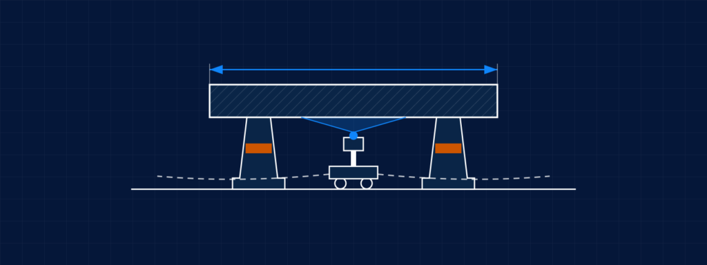
Agitation adds complexity. A mixing vessel might use a drum or a removable tub rather than a fixed vessel, and the impeller has to sit at the right depth across different liquid levels and batch sizes. These vessels are often mounted on load cells, and lowering the mixing head into position can corrupt the reading if the connections are rigid. Flexible connections at the mixing head keep the load cells reading the batch rather than the equipment above it.
The most dangerous reactor scenario is a runaway exothermic reaction. Polymerization reactions are highly exothermic. Acrylic acid, for example, can undergo a runaway polymerization that happens very quickly and produces a large volume of vapor. Managing that risk requires properly sized relief devices, jacket cooling that can respond to the heat load, and inhibitor strategies. Inhibitors can be pre-mixed in solution with the chemical, though that may affect the desired reaction, or added through separate systems that activate when a temperature threshold is reached. Process hazard analysis defines the scenarios, and SIL 2 or SIL 3 safety integrity levels may require redundant instruments to maintain temperature control within safe bounds.
Material Selection
Material compatibility is the most expensive thing to get wrong. If the wrong material is specified and the process destroys it, the equipment has to be replaced entirely, and the cost covers both the equipment itself and the labor to remove the failed unit and install its replacement. Unlike a resizing error, there is no partial remedy, because the wetted material cannot be changed without changing the equipment.
The decision between carbon steel, stainless steel, exotic alloys like Hastelloy, and specialized liners such as glass or PTFE is driven by what is in the pipe and the operating temperature. Higher temperatures increase corrosion risk significantly. The price difference between these materials is substantial, so the goal is to match the material to the process without specifying more corrosion resistance than the process requires.
Material compatibility tables are a reasonable starting point, but temperatures above the ranges indicated or any other ambiguity requires additional investigation, potentially including lab testing.
Vessel inspections offer a practical fallback. Measuring metal thickness over time reveals the actual corrosion rate, and in some cases a less resistant material can be used if the inspection program is adequate to catch degradation before it becomes a problem. That approach is not ideal, but it recognizes the reality that even Hastelloy will corrode under certain conditions.
Failures related to material compatibility recur across the industry, and most trace back to specification decisions made before the full operating conditions were defined. The following example shows the cost of a mismatch on the heat transfer side rather than the corrosion side. A poly tank had been specified for diluting caustic, a process that generates heat. The temperature from the dilution reaction exceeded what the poly material could handle, and the facility had to buy new tanks with cooling systems. Nothing corroded. The material simply could not take the heat.
Heating, Cooling, and Temperature Control
There are multiple approaches to managing temperature on a reactor or vessel, and the right choice depends on what utilities are available in the plant and what the process requires.
For heating, many installations use a tempered water loop rather than running steam directly to the vessel jacket. A steam-water heat exchanger heats water, which is then recirculated through the jacket. This eliminates the need for steam traps and other infrastructure on the vessel itself, which is a meaningful simplification because steam is tricky to design around on vessels. An alternative to steam entirely is an electric heating coil in the tempered water unit.
For cooling, a common arrangement is also a tempered water loop where central plant chilled water is used to cool a separate, localized tempered water loop. This gives precise temperature control, prevents the process fluid from freezing or fouling on the heat transfer surface, and isolates the main chiller utility.
Every heating and cooling option traces back to its energy source. Heating comes from natural gas, producing steam, or from electricity. Cooling comes from evaporative cooling through a cooling tower open to atmosphere, from a closed-loop chilled water system using refrigerant, or from a combination of the two, such as a cooling tower paired with a scroll chiller. The closed-loop system reaches lower temperatures than an open tower on its own.
Valves
A plant might have thousands of valves, and each one serves a specific function. The process equipment selection starts with two questions: what is the valve’s function, and what is in the pipe?
A valve’s function may be one of many, including flow control for the process, isolation for maintenance (taking equipment out of service for cleaning, repair, or replacement), or flexibility for future tie-ins. The media in the pipe determines the valve type beyond its basic function. The options include ball, plug, diaphragm, needle, globe, gate, and butterfly valves, among others, and the function and media have to be considered together.
Valve count causes more field problems than valve type. Plants built with cost efficiency in mind may not have all the valves they need, particularly for maintenance. Running a process requires valves, and maintaining a process requires more of them. Equipment must be isolated for service. Piping must be drained, flushed, and locked out before anyone opens it up for maintenance. Depending on the process, lockout may require a double block and bleed arrangement, which means at least three valves on each line going to a piece of equipment. Making sure all the valves are in place at commissioning is far easier than adding them later, because adding them later requires the very isolation capability that is missing.
Specifying a valve goes well beyond selecting the type. A ball valve on a datasheet is a full port, 316 stainless steel ball valve with a lockable handle, rated for the temperature and pressure of the service, and that is still just the beginning. Seats and seals, gaskets, fasteners, connections, stems, handles, gear operators, and spring return mechanisms all need to be specified for each application. Ratings matter down to the smallest component. Gaskets that are fine at ambient conditions will disintegrate in high temperature service.
Control valves introduce their own sizing challenges, and most of them trace back to the pressure assumed available at the valve. It is easy to assume 5 psid will be there at the design point, but that assumption may not hold at actual operating conditions. At higher flow rates, two effects compound: pressure loss in the piping increases, and if the flow is driven by a centrifugal pump, the pump is also dropping off the end of its curve. Both reduce the pressure available to the control valve, and sizing without accounting for them leaves a valve that cannot do the job when it matters most.
The error runs the other way just as easily. Size for an assumed 5 psid when 30 psid is actually available at design flow, and the valve comes out oversized. It then has to operate at a very low position, where control quality suffers. Assuming a low available pressure drop is not the safe choice it appears to be, particularly when the valve is responsible for taking a larger drop.
When a valve problem does appear, the instinct is to blame the valve. Sometimes that is correct, and the valve is worn out and needs replacement. Other times the root cause is in the controls, or somewhere else in the process entirely. An apparent problem with a flow loop might trace back to a pressure controller on a different line. A good valve will not compensate for poor controls, and better controls will not compensate for a bad valve. The system has to be evaluated as a whole.
Type selection creates its own control problems. Ball and butterfly valves get pressed into control service regularly, and neither performs well in that role. Purpose-built variants exist, including slotted ball valves and sharktooth butterfly valves, which control considerably better than the standard versions.
Level Sensing
Measuring liquid level in a vessel starts with a choice between contacting and non-contacting technologies, and the application determines which is appropriate. Non-contacting options include radar, ultrasonic transmitters, and load cells; contacting options include static head pressure measurement, capacitance, floats, and guided wave probes. Radar and guided wave are two of the most common, and they illustrate the trade-offs.
Non-contacting radar probes mount at the top of the tank and send a signal downward. The signal bounces off the liquid surface and returns to the receiver, and the time of flight determines the level. These probes can sometimes detect the interface between two immiscible fluids, such as oil and water, which separate due to differences in polarity and specific gravity. The limitation is that non-contacting radar is sensitive to vessel geometry, with specific requirements around nozzle spacing and proximity to vessel walls.
Guided wave probes, the contacting type, require the process fluid to be in contact with the probe at all times. They are less sensitive to vessel geometry, making them a better fit for installations where the vessel shape or nozzle locations create challenges for non-contacting probes.
The choice ultimately depends on the dielectric constant and reflectivity of the liquid being measured. Both liquid-liquid interfaces and solid-liquid interfaces can be detected, but the specific probe technology must be matched to the material properties of the process fluid.
Getting Process Equipment Specification Right
Every piece of process equipment selection in a process system is shaped by what surrounds it. Changes to the pump affect the control valve, the control valve affects the heat exchanger, and the vessel at the end of the line sets pressure, temperature, and material constraints that carry back upstream. Recognizing those interdependencies early and defining the process with specificity is the difference between a system that works and one that has to be redesigned after installation.
For questions about process equipment selection or system design, reach out to the C-P Systems engineering team.
Common Questions
What determines whether a vessel needs to be built to ASME code?
How does fouling affect heat exchanger performance, and what can be done about it?
What is the most expensive mistake a facility can make with process equipment?
What is the difference between a conventional jacket and a dimple jacket on a reactor?

Eric Sauer, P.E.
Senior Chemical Engineer
Eric Sauer, P.E., is a senior chemical engineer at C-P Systems with 18 years of experience across the ethanol and chemical manufacturing industries.

Ryan Wirtanen, P.E.
Chemical Engineer
Ryan Wirtanen, P.E., is a chemical engineer at C-P Systems specializing in relief valve design and equipment specification. He prepares relief calculations for new processes and existing vessels and holds a Professional Engineer license.