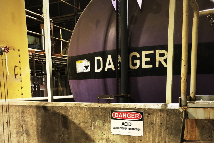
Anyone who works in an industrial or chemical manufacturing facility knows that relief devices aren’t optional. Relief devices are a frontline defense for personnel safety, environmental protection, and business continuity. While most engineers understand what relief devices do, the decisions that separate a well-designed system from a problematic one often come down to configuration, sizing, and monitoring.
Understand Your Process and Scenarios
Relief system design starts with the process itself. The engineer identifies every scenario that could lead to an overpressure condition, determines what materials are involved, and establishes the required relief rate. This is the foundation that every subsequent decision builds on.
API 521 provides guidance on overpressure scenarios, and PSM-covered facilities are required to evaluate these systematically. Getting this step right means having a clear picture of what could go wrong and what the system needs to handle.
Evaluate Materials of Construction
Relief valves are expensive, especially the larger ones. When highly corrosive chemicals are involved, the cost of a Hastelloy or Teflon-lined relief valve can be significant. A rupture disc made of the same exotic material is considerably less expensive than a full relief valve. In many cases, the economics of the process fluid drive device selection as much as the engineering does.
The capital expense alone is significant, but the lead time compounds it. Specialty alloys and lined components require specialized manufacturing, so replacements can take weeks or even months to arrive. If a relief valve fails or needs replacement, the facility could be waiting a long time before that system is protected again. A rupture disc of the same material can be sourced and installed much faster.
Choose the Right Device and Configuration
A relief valve is a resealing device. When the pressure exceeds the set point, it opens to relieve the excess. When the excursion passes, it re-seats. This is a significant advantage from an environmental standpoint because the system isn’t continuously off-gassing material that doesn’t need to be released. For systems where containment matters after the event, a relief valve is often the right call.
A rupture disc, on the other hand, is a one-time device. Once it relieves, the system is open. Everything can get in or get out. Each facility then has to commit to a shutdown and replacement before that system is protected again.
Why would anyone choose a rupture disc if a relief valve is resealing? The answer lies in cost and material compatibility, as discussed above.
Sizing the Relief Device
Once the device type and configuration are determined, the engineer performs the sizing calculations to determine how large the devices need to be. These calculations are based on the relief scenarios identified earlier and account for the specific properties of the process fluid.
Using Both in Series: Protecting the Relief Valve from the Process
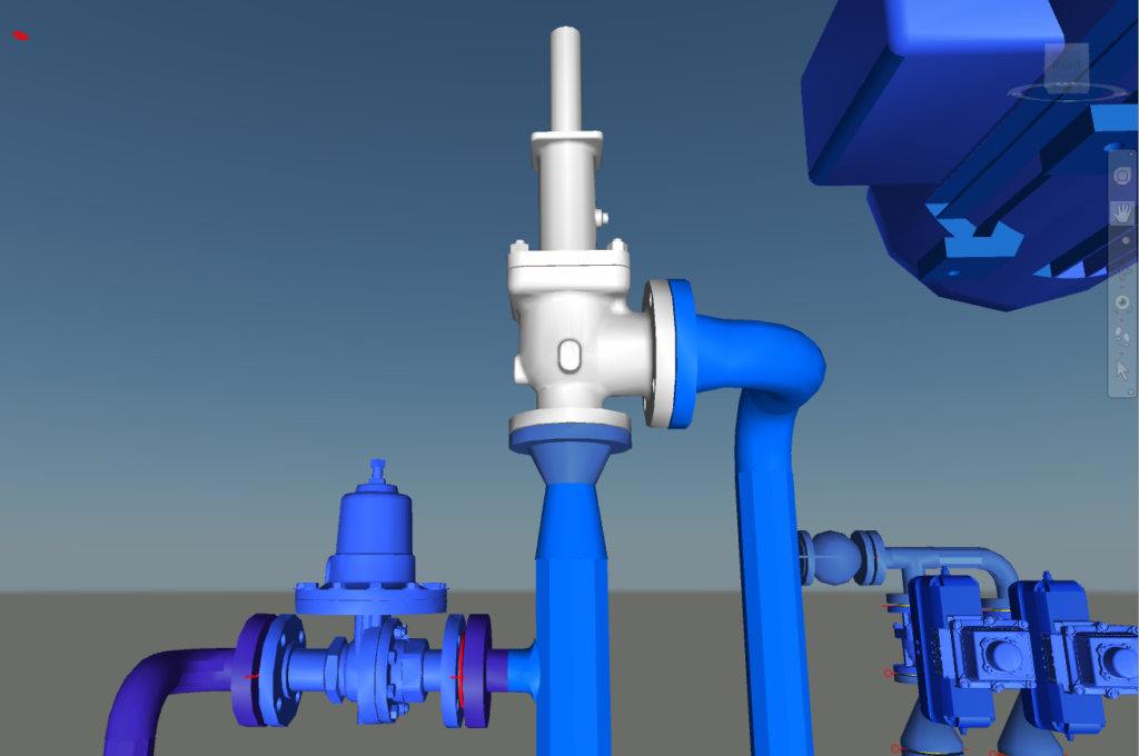
In practice, many systems use a rupture disc and relief valve in series. The logic is straightforward: the rupture disc sits on the process side and acts as a barrier between the corrosive or reactive material and the relief valve. This allows for a less expensive, more commodity-grade relief valve (carbon steel or stainless steel) while the rupture disc handles the material compatibility challenge.
The rupture disc is set to fail at nearly the same pressure as the relief valve’s set point. In a pressure excursion, the disc ruptures first, and the relief valve then opens to relieve the system. When the excursion ends, the relief valve re-seats, providing the environmental containment benefit of a resealing device while protecting it from the process fluid.
It’s an elegant solution, but it introduces a critical vulnerability that many facilities underestimate: the space between the two devices.
The Monitoring Gap: What Happens Between the Disc and the Valve
When a facility installs a rupture disc and relief valve in series, code requires some form of pressure indication between the two devices. These are called telltale indicators, and their purpose is to detect leaks or failures in the rupture disc before they compromise system safety.
Here’s why this matters: a rupture disc operates on differential pressure. If a facility develops even a small leak that bleeds pressure into the space behind the disc, that back pressure raises the threshold at which the disc will actually rupture. A disc set for 150 PSI with 10 PSI of back pressure behind it now requires 160 PSI inside the vessel before it will relieve. In this scenario, the system has quietly become unsafe. Without monitoring, no one may know it until the next scheduled inspection, or worse, until a pressure event reveals the problem.
Facilities generally have three options for monitoring this space, and the choice has real consequences for safety and operational risk:
Pressure Indicator (Gauge)
This is the lowest-cost option. It is a manual gauge that maintenance personnel check on a regular schedule, typically monthly. The limitation is obvious: if a leak develops five minutes after an inspection, the system could be unsafe for the entire interval until the next check. If maintenance finds pressure on the gauge, it may require an immediate shutdown to address, which can mean scrapping a batch of material and unplanned downtime.
Pressure Switch
This is a step up from the manual gauge. A pressure switch triggers an alarm when pressure exceeds a set point, providing more timely notification than a monthly walkdown. However, it’s binary. It tells the facility there’s a problem once the threshold is crossed, but it doesn’t show how pressure has been trending over time. A significant leak gets caught, but a slow, gradual buildup could easily be missed.
Pressure Transmitter
This is the most robust option and what our team generally recommends. A pressure transmitter provides continuous data on how pressure between the devices is changing over time. It gives the best resolution for identifying developing problems. A slow leak building from 2 PSI to 5 PSI to 10 PSI over a period of days or weeks becomes visible early, allowing for a controlled maintenance intervention rather than a reaction to an emergency. The trade-off is a higher capital cost and the controls infrastructure needed to support it.
The monitoring decision is ultimately a cost-versus-risk calculation. From a safety standpoint, the transmitter provides the narrowest window of vulnerability. For facilities managing hazardous materials, that window matters.
Conservative vs. Under-Conservative: Finding the Right Balance
One of the most common pitfalls in relief system design is getting the level of conservatism wrong in either direction.
Being too conservative typically means assuming multiple independent failures will occur simultaneously, which leads to oversized relief devices. Oversized valves aren’t just expensive; they can also cause operational problems. A valve that opens and closes with insufficient flow can chatter, which leads to premature valve failure and makes the device itself unreliable.
Being under-conservative means assuming that instruments never fail, that operators never make mistakes, and that systems always behave as designed. That’s where real trouble starts, because equipment does fail, human error is inevitable, and systems rarely behave perfectly over time.
API 521 provides guidance on this through the concept of double jeopardy. The general principle is that a relief system should be designed to handle one failure. We assume that the system operates normally, and the relief device accounts for a single upset condition. Two truly independent failures occurring simultaneously (double jeopardy) generally don’t need to be considered.
The nuance that many engineers miss is the distinction between independent failures and linked failures. If an electrical failure closes multiple valves simultaneously, that’s a single failure with multiple consequences, not double jeopardy. Understanding that distinction is critical to identifying credible scenarios and sizing relief devices appropriately.
Relief Calculations: When Material Data Doesn’t Exist
Not every material that runs through a facility has well-documented physical properties. Proprietary chemicals, intermediates, and high-viscosity materials often lack the published data that relief calculations depend on.
In some cases, the facility can confirm that a material is sufficiently similar to a well-characterized chemical, and we can use that as a basis for calculations. But when there’s genuine uncertainty, particularly around reactivity or thermal behavior, then third-party testing is the responsible path. Facilities like those offering VSP2 testing can characterize a material’s behavior under conditions relevant to relief scenarios.
High-viscosity materials present their own challenge. The way a shear-thinning or shear-thickening fluid moves through piping and components can significantly affect relief system performance, and those rheological properties need to be accounted for in the design.
Every assumption that goes into a relief calculation should be documented, justified, and reviewed collaboratively with the process owner. That step protects the facility, the design, and the people who depend on both.
Documentation and Revalidation: The Ongoing Obligation
For PSM-covered facilities, relief system documentation is an ongoing obligation. Calculations need to be revalidated, at least every five years, and any time a process change occurs, the relief calculations should be reviewed to confirm they’re still adequate.
The relief system that was right for the original design may not reflect current conditions, and that’s not a failure of the original engineering. It’s the natural result of a facility that’s operating and growing. The facilities that stay ahead of their revalidation cycle and revisit calculations with every process change are the ones that walk into audits with confidence. (For an example of how we’ve helped facilities close these gaps, see our relief study case study.)
The documentation itself is what proves the system is safe. A well-designed relief system paired with thorough documentation is both the strongest compliance position and the strongest operational one.
Closing
The facilities that call us most often are working through a process change, inherited a system from a previous owner, or realized during a HAZOP that nobody can locate the original relief calculations. These are common situations, and they are fixable.
If there are questions about a current relief system configuration or a need to bring documentation into compliance, contact us.